(课堂笔记)第十三章:DNS 全局站点
——-外网DNS架构————–
——-Inbound DNS配置———-
——-GSLB全局负载————-
——-外网DNS架构————–
1.1 术语:
Data centers:组织server的容器,表述一个具体的数据中心。
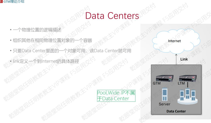
Servers:用来代表一个server实体,类似于LTM中的node,有bigip server,non-bigip server两类,隶属于datacenter中,同一server不应同时存在于两个datacenter;(简单来说,所有F5设备组成1个servers,当Active配置变化时,将推送给组内其他成员)
link:代表datacenter中的链路,与Data centers关联;(运营商线路)

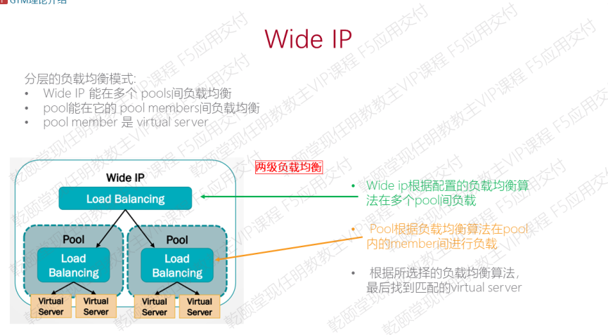
Pool:用来组织VS,是wideip的配置要素,同一VS可以同时属于多个pool;(域名下来并不是直接对VS IP,而是pool)

Prober Pools(探针池):指定F5 DNS去检测各种资源的可用性,Prober pools可以指派给F5 DNS里面的单个server也可以指派给F5 DNS里面的data center
Wideip:对外呈现的智能域名,其下包含pool。
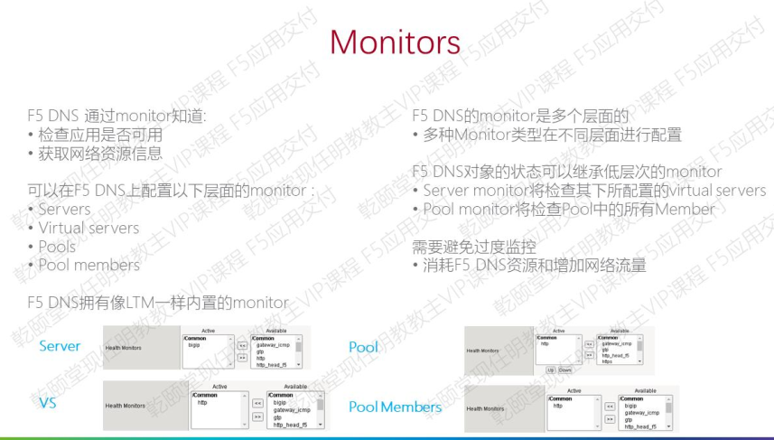
Monitos:健康状况,可以针对GSLB中servers、pool、pool member、virtual servers监控;
iQuery:F5私有协议,用于BIG-IP设备间传输SNAT表以及会话保持表等内容的传输协议
GTM:Global Traffic Manager,全球流量管理器。
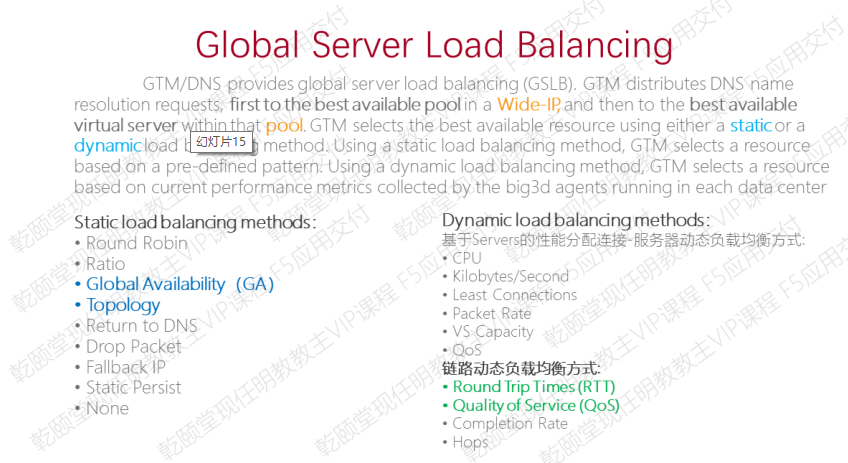
Global Server Load Balancing:全局负载算法,分静态及动态,各有:
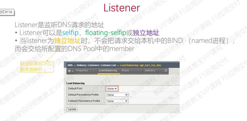
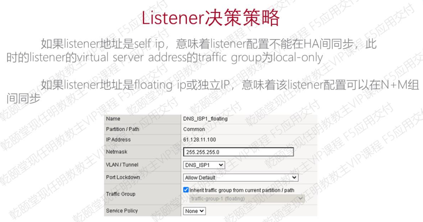
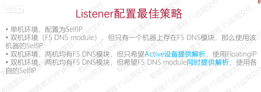
listener:监听DNS请求和服务。与wideip关系为wideip-listener–pool–vs(不属于gslb,不会自动同步listener配置,属于LTM,可LTM同步)
——-Inbound DNS配置———-
2.1 配置查询回应日志
《1》配置logging Profile
“system”-“logs”-“configurations”-“log publishers”
name填写“local-syslog-publishers1”
Destinations中将“local-syslog”调整为“selected”状态
《2》DNS logging profile
“DNS”-“Delivry“-“prifiles”-”other“-”DNS logging“
name填写“DNS_logging_profile1”
logging publishers 选择“local-syslog-publishers1”
《3》DNS profile
“DNS”-“Delivery”-“profiles”-“DNS”
name填写“qytangcciedc.com_dns_profile1”
Unhandled Query Action 选择“DROP”
Use BIND Server on BIG-IP 选择“Disabled”
logging 选择“Enable”
logging Profile选择“DNS_logging_profile1”
AVR Statistics Sample Rate选择”Enabled“,比例填写1:1
《4》配置udp profile
“DNS”-“Delivery”-Profiles“-Protocol”-“UDP”
name填写“udp-dns_profile1”
Datagram LB选择“Enable”
《5》配置tcp profile
“DNS”-“Delivery”-Profiles“-Protocol”-“TCP”
name填写“tcp-dns_profile1”
Paraent Profile填写“f5-tcp-wan”
《6》配置DNS linsterner
“DNS”-“Delivery”-“Listeners”-“Listener List”
name填写“isp1_DCI_ns.qytangcciedc.com_udp_53_virtual”
Destination中Address填写“61.128.0.4”
Service选择“Advanced”高级:
Protocol选择“UDP”
Protocol Profile(Clinet)选择“udp-dns_profile1”
DNS profile选择“qytangcciedc.com_dns_profile1”
name填写“isp2_DCI_ns.qytangcciedc.com_udp_53_virtual”
Destination中Address填写“128.61.0.4”
Service选择“Advanced”高级:
Protocol选择“UDP”
Protocol Profile(Clinet)选择“udp-dns_profile1”
DNS profile选择“qytangcciedc.com_dns_profile1”
name填写“isp1_DCI_ns.qytangcciedc.com_tcp_53_virtual”
Destination中Address填写“61.128.0.4”
Service选择“Advanced”高级:
Protocol选择“TCP”
Protocol Profile(Clinet)选择“tcp-dns_profile1”
DNS profile选择“qytangcciedc.com_dns_profile1”
name填写“isp2_DCI_ns.qytangcciedc.com_tcp_53_virtual”
Destination中Address填写“128.61.0.4”
Service选择“Advanced”高级:
Protocol选择“TCP”
Protocol Profile(Clinet)选择“tcp-dns_profile1”
DNS profile选择“qytangcciedc.com_dns_profile1”
验证:可在LTM-VS上看到2个IP的53端口(共4个条目)
《7》配置Data centers和link
“DNS”-“GSLB”-“Data Centers”-“Data Centers List”
name填写“qytangdc1”
点击完成
name填写“qytangdc2”
点击完成
“DNS”-“GSLB”-“links”-“Add:
name填写“HTTP-ISP1”
Address填写“61.128.0.6”,并点击“Add”
Data Center 选择“qytangdc1”
Health Monitors 选择“gateway_icmp””
点击完成
name填写“HTTP-ISP2”
Address填写“128.61.0.6″,并点击“Add”
Data Center 选择“qytangdc1”
Health Monitors 选择“gateway_icmp””
点击完成
《8》配置servers
“DNS”-“GSLB“-“Server”-“Servers List”
name填写“DC1-DNS-HA”
Date Center选择“qytangdc1”
Device中点击“Add”
Device Name填写“DC1-DNS2.qytang.com”
Address填写自己的self ip”61.128.0.3″和”128.61.0.3″-finish(DC1-DNS2)
Device中点击“Add”
Device Name填写“DC1-DNS1.qytang.com”
Address填写自己的self ip”61.128.0.2″和”128.61.0.2″-finish(DC1-DNS1)
configurations中的“Health Monitors”将“bigip”调整为Active状态;
Resources中的virtual Server Discovery选择”Enabled“,Link Discovery(自动发现)选择”Enabled“
可以在“DNS”-“GSLB“-“Server”-“Servers List”-“Device”-“DC1-DNS-HA”看到自己端是绿色的,对端是蓝色的,证明链路还没有建立。
Device中点击“Add”
name填写“DC1-LTM-HA”
Date Center选择“qytangdc1”
Device Name填写“DC1-LTM2.qytang.com”
Address填写自己的self ip”172.16.10.253″(DC1-LTM2)
Device中点击“Add”
Device Name填写“DC1-LTM1.qytang.com”
Address填写自己的self ip”172.16.10.252″-finish(DC1-LTM1)
configurations中的“Health Monitors”将“bigip”调整为Active状态;
Resources中的virtual Server Discovery选择”Enabled“,Link Discovery(自动发现)选择”Enabled“
可以在“DNS”-“GSLB“-“Server”-“Servers List”-“Device”-“DC1-LTM-HA”看到自己端是绿色的,对端是蓝色的,证明链路还没有建立
《9》配置Device Trust
为什么要交换证书:为了F5 BIG-IP设备设备间通信iQuery;
有三个命令可以交换机F5 BIG-IP的设备间的证书:bigip add、big3d_install、gtm_add;
以上三个命令应在F5 DNS上执行:
a.bigip add 只用来交换证书,使用SSH协议和scp命令;
b.big3d_install 推送big3d程序给对方+交换证书;
c.gtm_add拉取对方配置到本机+交换证书+将自己加入DNS同步组
iQuery通信:
正确交换完证书是iQuery mesh结构建立的前提;
(1)iQuery F5私有协议使用TCP 4353端口,使用SSL加密通信,实际传输的是gzip压缩的XML数据;
(2)iQuery负责bigip间的monitor、heartbeat、path metiric collection result、persistence的交换或同步,是各种configurations(bigip、gtm、conf、named、conf、zone)同步的执行者
(3)big3d在所有self ip,内部接口包括mgmt上监听tcp 4353;
(4)iQuery是gtmd与big3d之间的通信,所以iQuery mesh是gtm与gtm,gtm与ltm之间的mesh。ltm只是单向传送iQuery到GTM,不主动发起iQuery连接;
(5)查看F5 4353端口情况: netstat -tnlp | grep 4353
bigip_add 61.128.0.2(在DC1-DNS2-F5上)
bigip_add 172.16.10.252(在DC1-LTM2-F5上)
检查是否交换机证书:DNS”-“GSLB”-“Servers”-“Trusted Server Certificates”中“Certificates Subject(S)“中发现是有远程的设备
《10》dns pool
“DNS”-“GSLB“-“Pools”-“Pool List”
name填写“GLSB-web-pool”
Type选择“A”
configurations中的Health monitors,这里选择适用tcp协议来监控,tcp调为Active状态;
Member中的load balancing method中,preferred选择“Topology”,Altemate选择“None”,Falback选择“Global Availability”
Member List中的virtual Server选择两台LTM设备的VS地址(172.16.0.5/6)
《11》WideIPs
“DNS”-“GSLB“-“Wide IPs“-”Wide IP List“
name填写“www.gslb.qytangcciedc.com”
Type选择“A”
Pools中的load Balancing Method选择“Topology”,Pool List中的pool选择步骤10建立的“GLSB-web-pool(A)”–“Add”
点击完成
配置好以后,在ISP1-win7上测试下:cmd敲“dig @61.128.0.4 www.gslb.qytangcciedc.com”发现解析出IP为LTM上的私网地址(172.16.10.5/6)
回到DC1上随意一台F5设备,在“DNS”-“GSLB“-“Server”-“Servers List”-“Virtual Servers”-“DC1-LTM-HA”,virtual Server Discovery选择“Disabled”
创建Virtual Servers中“DC1-LTM-HA”的新Virtual Servers:
name填写“HTTP-ISP1”
Address填写”61.128.0.6“
Transiation Address填写“172.16.10.5”,Server port选择“80”“HTTP”
LINK选择“61.128.0.1”
configuration中的Health Monitor使用TCP协议通信,调为“Active”状态;
name填写“HTTP-ISP2”
Address填写”128.61.0.6“
Transiation Address填写“172.16.10.6”,Server port选择“80”“HTTP”
LINK选择“61.128.0.1”??
configuration中的Health Monitor使用TCP协议通信,调为“Active”状态;
配置好以后,在ISP1-win7上测试下,提示:no servers could be reached
这是因为步骤10中建立的“GLSB-web-pool“的virtual Server需要新建。
“DNS”-“GSLB“-“Pools”-“Pool List”-“GLSB-web-pool“-“Member”-”Add“,增加2个公网的VS即可。
添加完发现第二个IP(128.61.0.6)unlicensed状态,因为该功能需要授权,且只限于美国地区:(https://support.f5.com/csp/article/K15834)
name填写“GLSB-web-pool-DC1-ISP2”
configurations中的Health monitors,这里选择适用tcp协议来监控,tcp调为Active状态;
Member中的load balancing method中,preferred选择“Topology”,Altemate选择“None”,Falback选择“Global Availability”
Member List中的virtual Server选择unlicensed状态的ip(128.161.0.6)
这样配置2个pool,pool的负载均衡topology方式就废了,可以检查:
tmsh show gtm wideip A www.gslbcciedc.com detail 在Load Balancing中preferred没有命中(网页这里配了topology负载),而是其他的命中了
《12》DNS同步组
(在DC1-DNS1和2上:)
“DNS”-”Settings“-”GSLB“-”General“
勾选“Synchroize”以及“Synchroize DNS Zone Files”
Group Name填写“QytangDC-DNSG”
点击完成
《13》DNS迁移
在DC1-DNS1上拉取配置,命令:gtm_add 61.128.0.3
——-GSLB全局负载————-
《1》DC2上创建listener
“DNS”-“Delivery”-“Listeners”-“Listener List”
name填写“isp1_DC2_ns.qytangcciedc.com_udp_53_virtual”
Destination中Address填写“62.129.0.2”
Protocol选择“UDP”
DNS profile选择“dns”
name填写“isp2_DCI_ns”.qytangcciedc.com_udp_53_virtual”
Destination中Address填写“129.62.0.2”
Protocol选择“UDP”
DNS profile选择“dns”
(这里的配置跟DC1有出入,只为快速显示效果,没有配置DNS Profile和Protocol Profile(Clinet)属性;)
《2》DC1上添加BIG-IP类型的Server DC2-DNS
(DC2-F5-DNS由于有公网,可以直接填写公网的self ip(62.129.0.2或129.62.0.2)来建立server)
回到DC1-F5-DNS上:
“DNS”-“GSLB“-“Server”-“Servers List”-“Add“
name填写“DC2-DNS”
Date Center选择“qytangdc2”
Device中点击“Add”
Device Name填写“DC2-DNS.qytang.com”
Address填写自己的self ip”62.129.0.2 “和”129.62.0.2 “-finish(DC2-DNS)
Resources中的virtual Server Discovery选择”Disbled“
virtual sever list中:
name填写“DC2-HTTP-ISP1”
Address填写“62.129.0.3”
service Port选择“80”“HTTP”
Traslation填写“172.16.20.3”
Translation Port选择“80”“HTTP”
最后点击“Add”
name填写“DC2-HTTP-ISP2”
Address填写“129.62.0.4”
service Port选择“80”“HTTP”
Traslation填写“172.16.20.4”
Translation Port选择“80”“HTTP”
最后点击“Add”
Link Discovery(自动发现)选择”Disbled“
点击完成。
《3》DC1上添加BIG-IP类型的Server DC2-LTM
DC2-F5-LTM原应该通过内网来建立iquery,但是设计通过公网地址传输(不建议),所以要在DC2-F5-DNS上左NAT:
“Loacl Traffic”-“Address Translation”-“NAT List”
name填写“LTM-iQuery-NAT”
NAT Address填写“62.129.0.8”
Origin Address填写LTM地址“172.16.20.254”
点击完成。
回到DC1-F5-DNS上:
“DNS”-“GSLB“-“Server”-“Servers List”-“Add“
name填写“DC2-LTM”
Date Center选择“qytangdc2”
Device中点击“Add”
Device Name填写“DC2-LTM.qytang.com”
Address填写刚才做的NAT地址“62.129.0.8”
Translation填写刚才做的NAT转换后的私网地址“172.16.20.254”
Resources中的virtual Server Discovery选择”Disbled“,Link Discovery(自动发现)选择”Disbled“
点击完成。
在DC1-F5-DNS上:
bigip_add 62.129.0.2
bigip_add 62.129.0.8(NAT地址)
《4》DC2上添加DC2-DNS到DNS同步组
“DNS”-”Settings“-”GSLB“-”General“
勾选“Synchroize”以及“Synchroize DNS Zone Files”
Group Name填写“QytangDC-DNSG”
点击完成
采取命令拉取GTM配置(DC2-F5-DNS上):
#
gtm_add 61.128.0.3
#
拉取后检查GTM的配置是否同步拉取到DC2的DNS上,发现link部分没有,手动创建:
“DNS”-“GSLB”-“link”-“Data Centers List”-“Add”
name填写“DC2-ISP1”
Address填写“62.129.0.1”,并点击“Add”
Data Center 选择“qytangdc2”
Health Monitors 选择“gateway_icmp””
点击完成
name填写“DC2-ISP1”
Address填写“129.62.0.1,并点击“Add”
Data Center 选择“qytangdc2”
Health Monitors 选择“gateway_icmp””
点击完成
《5》DC1上添加DC2的wide-ip vs pool
“DNS”-“GSLB“-“Pools”-“Pool List”
name填写“GLSB-web-pool-DC2-ISP1”
Type选择“A”
configurations中的Health monitors,这里选择适用tcp协议来监控,tcp调为Active状态;
Member中的load balancing method中,preferred选择“Topology”,Altemate选择“None”,Falback选择“Global Availability”
Member List中的virtual Server选择DC2的ISP1(62.129.0.3)
点击完成
“DNS”-“GSLB“-“Pools”-“Pool List”
name填写“GLSB-web-pool-DC2-ISP2”
Type选择“A”
configurations中的Health monitors,这里选择适用tcp协议来监控,tcp调为Active状态;
Member中的load balancing method中,preferred选择“Topology”,Altemate选择“None”,Falback选择“Global Availability”
Member List中的virtual Server选择DC2的ISP1(129.62.0.3)
点击完成
“DNS”-“GSLB“-“Wide IPs“-”Wide IP List“
点击“www.gslb.qytangcciedc.com”-“Pools”-“Manage”
添加刚才新建的2个pool池(“GLSB-web-pool-DC2-ISP1”和“GLSB-web-pool-DC2-ISP2”)
点击完成
《6》BIG-IP配置Topology
涉及算法的具体内容,这里跳过。
原文链接:https://www.cnblogs.com/key-network/p/13817172.html


